Many of us are so used to merely turning on a tap nowadays that we cannot visualise what it was like before a mains water supply became available. As recently as 100 years ago, most people had to make their own arrangements to obtain water and this often meant taking it from the nearest river or stream. This had its dangers in that they never knew what had been placed in further upstream and disease was common. The use of a stream was not always possible, however, and the chalk areas of Kent and Sussex are usually completely devoid of surface water. The only answer was to dig down to find water and wells were essential in such places. The possession of a well was thus not only more convenient but also much safer, since the water had usually been filtered in passing through the surrounding rock. At one time, each village had its own communal well but, by the end of the 19th century, most houses had their own.
The depths of wells is governed by the level of the local water table, which is the highest point at which the rock is completely saturated with water. Near the coast, the water table will be at or near sea level but this rises further inland at a gradient of about 1 in 200. It is not as simple as this, however, since some layers of rock are impervious and the water draining down from surface cannot go any deeper once it has reached this point. The rock above this impervious layer thus becomes locally saturated and there is a ‘perched’ water table much higher than normal. Conversely, there are occasions when strata occurs at an angle and water bearing rock is overlain by an impervious layer. Surface water enters the lower layer some distance away and travels sideways to saturate the whole length of that layer. At a particular point, therefore, the ‘normal’ water table could be a great deal higher than it is but the water is prevented from rising to that point by an impervious layer above. Once the impervious layer is pierced, water is forced up under pressure and some low-lying wells actually have water flowing over the top! This is the principle behind artesian wells and the advantage is that the water does not have to be pumped out. As soon as a well has been sunk, water will seep in until the water reaches its natural level and this is called the ‘Rest Water Level’ (or RWL). In some areas towards the end of the 19th century, so much water was being extracted that the water table dropped and many wells had to be deepened when they ran dry. Nowadays, much of our water supply comes from surface reservoirs and the RWL of old wells has risen again as the water table returns to normal.
Wells have been dug for centuries and most were excavated by teams of professional well diggers. These were an itinerant breed of men who wandered the countryside and it is likely that they turned their hand to digging denehole shafts when work was slack. They were summed up by John Bannister in 1799:
‘. . . These accidents render this profession extremely hazardous, but as the people who embark in it entertain but little thoughts of a future period, and since the chief end of their pursuits is the obtaining of a liberal supply of drink, if this end be answered they bestow little attention to the hazards of their profession . . . ‘
A well was started by marking off a circle on the ground, 18 inches greater in circumference than the intended dimension of the well. A wooden platform was then laid down with a hole cut out corresponding to the required diameter. A tripod was erected over the hole and a windlass placed to one side. Due to the restricted space in the well, the tools used by the digger all had small handles and the most commonly used were a mattock-like pick and a round faced shovel called a ‘graft’. A wicker basket with two handles was used to remove the spoil and this was placed between the digger’s legs whilst working. Two tallow candies were placed on either side of the shaft and this gave light without casting a shadow. The digger descended by sitting on a horizontal stick which was tied onto the bottom of the rope. This was quite comfortable and he could sit on this for some hours, especially when installing the well lining.
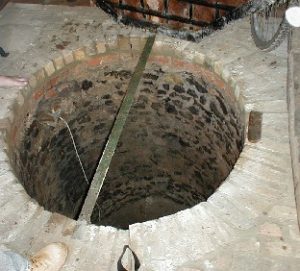
One of the first problems was to hold back the loose upper strata until solid rock was reached and, for this, a lining to the sides was necessary. This lining was called ‘steining’, and either bricks, stone blocks or flints were used. The local expression for bricking a well was ‘steaming up’ and the quality of the brickwork depended on how much the customer was prepared to pay. A good steining consisted of bricks laid lengthwise (stretchers) and sometimes these were doubled if the shaft was sunk through loose sand. Another method was to lay bricks end on (headers) and a course of headers was sometimes mixed with stretchers to give extra stability. In cheap wells, old reject half bricks (bats) were used and the ends were chipped to fit into the curve of the shaft. Since the soil behind would usually keep brickwork in place, steining was normally laid ‘dry’ except for the top 3ft which was mortared.
Two main methods of sinking were used. In the first, the well was sunk as far as it would go without failing in and then a circular ‘curb’ was laid at the bottom. The curb was made of sections of 4 inch thick wood, joined together, and the steining was built up on this to the surface with earth packed firmly behind it. A small pit was then dug in the centre of the floor and a platform of boards laid at the bottom. Notches were cut in the wails and lengths of timber called ‘raking props’ jammed in to support the curb above. The earth below was then excavated to the full diameter and another curb laid at the bottom, with steining installed up to the upper curb. The sections of the upper curb were then removed and steining inserted to make it continuous. This sequence was repeated until solid rock was reached, at which point a ledge was cut out for the whole steining to rest upon.
In the other method, a ‘tun’ was used which looked like a large barrel with half the staves removed. It was 6ft high, the diameter of the well without steining and the vertical boards were 1 inch thick was a spacing of 4-6 inches. The tun was lowered as the shaft was sunk and it gave protection to the digger working inside. When it reached a depth of 6ft, the tun formed a base on which the steining was built up to the surface. The digger then excavated underneath the tun, which sank at the same time under the weight of the steining. As soon as a further 6ft had been sunk, an extra section of steining was added to take it to the surface. In this way, the well was sunk until solid rock was reached and the steining followed the tun down the shaft, with more being added to the top as it progressed. A ledge was cut in the rock for the steining to rest upon and the tun removed. if solid rock was not reached, the tun was abandoned at the bottom of the well.
Once solid rock was reached, the sides no longer needed support but progress depended on how hard the rock was. Chalk was easily excavated by hand pick but some other types of rock needed explosive. Below about 40ft, bad air became a problem and this was especially so in chalk which produced carbon dioxide, a gas that is heavier than air. Various methods of ventilation were used, some quite bizarre but effective. Quick lime in a bucket was often lowered to the bottom at night and this usually absorbed bad air by the time work started in the morning. If not, a bale of hay was tied to the rope and thrown down the shaft a few times, thus forcing fresh air to the bottom. One local practice used a large upended umbrella which had the same effect! Before descending a shaft in the morning, the digger would test the air by lowering a candle in a bucket.
The usual method was to charge a certain price for sinking to solid rock and then agreeing a new price for each subsequent 20-25ft. This allowed the well diggers to take account of any unsuspected problems such as very hard rock or a layer of shifting sand. In the latter case, a special tun was made with bowed sides which were pulled in with an iron band. When placed in position, the band was removed and the sides automatically pushed outwards to jam the tun at that point. The decision on how deep to sink the well was fairly easy but very much ‘rule of thumb’. The well was considered deep enough if, first thing in the morning, it took more than an hour to empty it by continuous bailing. Other diggers stopped when the water was thigh deep or they were excavating one part of water to two parts of spoil.
Sometimes the water was so deep that a borehole was sunk instead or even a well sunk so far and then continued as a borehole. The advantage of a borehole was that it was quicker and cheaper to sink but it could not be descended subsequently like a well if maintenance was needed. In clay and soft rock, a large auger was used which was manually turned at the surface. In harder rock, however, it was necessary to use a chisel bit attached to a rope which, by being alternately raised and dropped, would break up the rock. After a short period of boring, the chisel bit was removed and a shell-pump lowered. This was a cylinder with a hinged bottom opening upwards and, when dropped into the hole, would trap the debris which could be pulled up with the shell-pump.
Domestic Wells
These were from 3-4ft in diameter and normally covered with a wooden lid or slab, water being pulled up by a bucket on a rope. Some were more elaborate with low brick walls at the surface and a windlass operated by hand or horse. Most were sited in the back garden near the house and many old houses still have their wells, albeit covered over and forgotten. With the introduction of terraced housing, it became impracticable to have a well for each house and there was usually a communal one for several houses, reached from the alley to the rear. When old houses are demolished for redevelopment, the old wells are often forgotten about and there have been a number of subsequent subsidences when the well cover has given way.
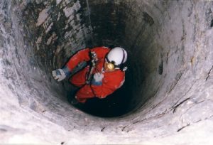
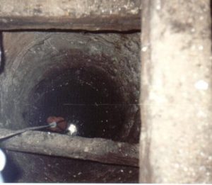
A domestic well was recently discovered under the floor of Yokes Court near Frinsted and this was pumped out and explored by members of Kent Underground Research Group. It was over 300ft deep but rubble had been thrown in at some time in the past and the original bottom was not reached. An interesting feature was that footholds had been cut into the sides of the well to a depth of 200ft, presumably when it was being sunk. In the room above, one of the exposed beams had a notch cut out where a pulley wheel had obviously assisted in pulling up the buckets of water. A more interesting haulage device was used at a well at St Radigund’s Abbey near Dover. This dates from the 12th century and there is a special well house with a wooden ‘horse gin’. The latter consists of a vertical windlass with a horizontal beam that was pulled round by a horse. Although the well is reputed to be 450ft deep, the RWL was only 183ft in 1966. The horse gin is still in situ.
Agricultural Wells
As the name suggests, these supplied water for farm animals or orchards where there was no surface source. Stables of large estates often had their own well, as did remote barns where cattle were kept away from the main farm. Most growing crops had to rely on natural rainfall but where lack of water could be a disaster, such as remote orchards, a well was sunk as an emergency source. These wells were similar in structure to the domestic type and were usually covered with a slab. Examples of such remote wells are near Hucking in Kent and Canadia in Sussex. Sometimes wells occur in remote woods and it can be puzzling why they were ever placed there. These are usually the only visible remains of very old settlements which have since become disused and overgrown.
Industrial Wells
A number of large factories in the 19th century often needed a great volume of water and thus sank their own wells, with pumps to ensure a continuing flow. Since the extraction rate was much greater than a domestic well, they had to go deeper to ensure a continuing supply and often used boreholes. Where a traditional well was sunk, these were much wider and anything up to 10ft in diameter. Certain industrial processes needed soft water but there could be problems with ordinary wells, e.g. those near the coast could have brackish water and those in chalk gave hard water. The answer in this case was to sink right through the chalk to reach the Lower Greensand Beds which gave a supply of soft water, sealing off the well from the chalk layer to prevent intermixing. All disused brickfields and cement works would have had their own wells but these were often merely covered over when abandoned. An example of a brickfield well (with a 12-inch bore) is at Newgardens in Kent where the pumping apparatus was still in place at the time of writing.
With the introduction of mains water supply, wells did not become completely obsolete. Many Water Boards in areas on the chalk sank large wells to obtain the water that they treated and distributed. To increase the flow still further, horizontal passages were driven from the sides of the well for hundreds of feet so that a bigger area could be tapped. These systems are almost underground reservoirs and many are still used or kept as emergency supplies. A typical example is the Luton Pumping Station at Chatham where 10 separate wells have been sunk to 150ft and all are interconnected by headings to form one system. There is a total of over 5,000ft of these headings which average 9ft x 7ft in cross-section. The Ramsgate water supply is even larger with over 5 miles of horizontal passages. Some water authorities even drove horizontal wells into the chalk which consisted of branched adits with boreholes in the roof.


